
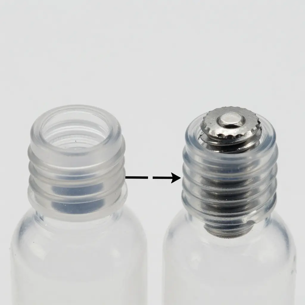
Diagnostic Brief: Defining Cross-Threading
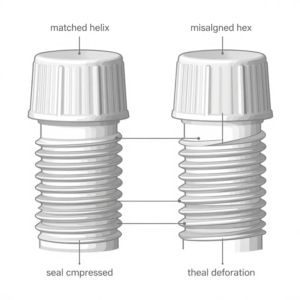
Cross-threading is a closure-application defect: the closure thread and the container thread do not sit in the same helix during application, so the two thread forms interfere instead of nesting. Engagement ends up partial or misaligned, the thread deforms, and the seal fails even when the cap looks seated.
Orientation decides the outcome, not force. A correctly applied closure travels one continuous helix from thread start to seating torque. A cross-threaded closure starts on a competing path, and the two thread forms fight each other from the first turn.
On screw cap plastic food containers the condition shows up in three measurable ways: a torque curve that rises early or spikes before seating; a deformed thread crest on the container or the closure, sometimes visible and often only under magnification; and a failed seal-integrity test on a cap that appears seated.
Central Analytical Claim
On the filling lines behind this brief, cross-threading traces back to neck finish mismatch – dimensional and geometric disagreement between container and closure – rather than to capping speed. Speed decides how fast a defect becomes visible across a run. It does not create the geometry that allows the defect in the first place. Chuck alignment, jaw wear and a cap presented off-square can also start a thread on the wrong path, which is why the measurement sequence later in this article is ordered to test those causes rather than assume them away.
The causal order runs from nonconforming neck geometry to a first-thread engagement point that lands outside the closure’s lead-in tolerance, and only then to visible cross-threading. Line speed and application torque sit downstream, which is why adjustments at the capper rarely hold.
How the Case Is Built
The argument runs on three kinds of evidence. First the defect mechanism: how an off-helix start loads the flank, and which torque signatures separate cross-threading from under-torque and over-torque. Then the dimensional evidence: neck finish drawings and measurement data showing where container and closure leave spec. Last, the supplier consequences – qualification and incoming inspection for plastic food containers – and a measurement protocol that a bottle supplier, a closure supplier and a filler can each audit.
The Thread Engagement Mechanism That Produces Cross-Threading
Proper thread engagement is not a sliding fit. It is the controlled interpenetration of two helices, and the capping stroke is easier to diagnose as a kinematic problem than as a handling problem.
The Helix Path
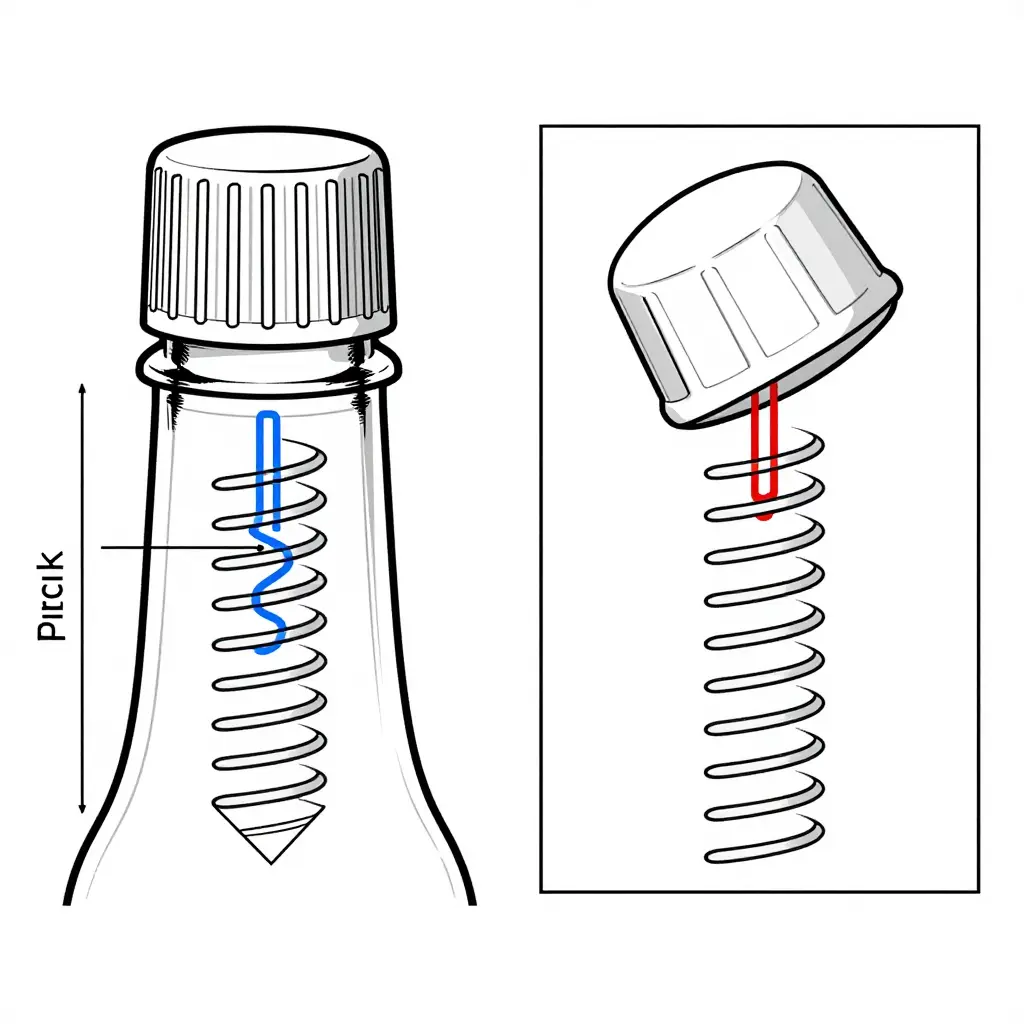
A container thread is a helix wrapped around the neck finish. Its thread pitch – the axial distance between corresponding points on adjacent crests – sets how far the closure advances per revolution, so on a single-start thread one full turn moves the cap exactly one pitch. Across the engagement turns a given closure uses (commonly 1.5 to 3.0 on food containers), the closure thread has to travel that helical corridor without ever touching crest-to-crest. The corridor is bounded radially by the thread root diameter, the base of the thread groove, and angularly by the flank angle, measured between the load-bearing thread face and a plane normal to the axis. Engagement succeeds when the closure flank lies against the neck flank across the full contact face and the crest floats clear of the root.
The Role of the Lead-In Chamfer
The lead-in chamfer is the truncated, ramped entry at the start of the thread. Because it presents a partial-height thread form, it can pass over the mating crest before full flank contact is established, which widens the entry window and funnels the closure thread toward the root. In effect the chamfer converts part of the axial stroke into a small rotary correction, and that is what lets a nominally vertical application motion find the helix. Its axial length and its angular position relative to the thread start set the geometric forgiveness of the pair. Once mismatch consumes that window, the correction cannot happen.
Three Quantities That Are Routinely Conflated
| Quantity | Definition | Physical Meaning |
|---|---|---|
| Application torque | The rotational moment applied by the capping head, in N·m or in-lb | Input energy, resolved by the helix into axial force plus friction |
| Axial pre-load | The clamping force generated along the closure axis | The force that compresses the liner and loads the sealing land |
| Engagement depth | The number of thread turns, or axial length of thread overlap | The load path that must exist before pre-load can be transmitted |
They are independent variables, and torque does not turn into pre-load on its own. Pre-load scales with applied torque divided by the effective helix radius, then corrected for friction on the flanks and for flank angle. Engagement depth is a geometric property: no amount of torque manufactures turns the thread form does not provide. A closure engaged on two crests receives the same torque as a seated one and converts it into crest deformation instead of sealing force.
How Mismatch Becomes Off-Helix Engagement
When the thread start of the closure and that of the neck are angularly offset – or their flank geometry differs – the leading edge of the closure thread lands on the neck flank instead of in the root. The flank angle is far steeper than the helix angle, so an axial stroke at that contact point resolves into a large flank-normal force. The cap is driven up the flank while rotating on a path that is not the thread’s, re-forming or shaving the thread as it travels. Flank angle mismatch produces the same outcome by reducing contact from full face to a line, and a pitch difference adds a lead error that grows with every engagement turn. Cross-threading is therefore a signature of geometric incompatibility, and it reproduces identically on any rigid container and closure combination carrying the same mismatch.
Failure Symptoms, Read Analytically
- Skewed caps – the closure axis is no longer collinear with the neck axis, because the off-helix contact point acts as an eccentric fulcrum.
- Incomplete seating – a measurable gap between liner and sealing land, since axial travel is spent climbing the flank rather than advancing along the helix.
- Cocked liners – the liner is displaced or tilted off its seat by non-axial rotation during engagement.
- Seal integrity loss – an uncompressed or unevenly compressed liner leaks, admits oxygen, or loses vacuum under pressure-decay or dye-penetration testing.
- Back-off after capping – removal torque (the moment required to start reverse rotation) falls below specification, because deformed crests and relieved elastic strain dissipate the pre-load that application torque was meant to store.
Every symptom traces to the same root cause: a thread pair that never reached full engagement depth on nested flanks.
Aligned and Cross-Threaded Engagement
The diagram below reduces the problem to its mechanism: two identical closure-container pairs, one behaving and one failing.
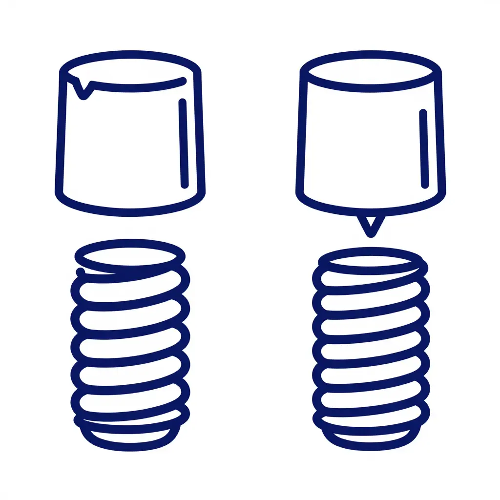
In the left panel the closure thread tracks the container helix and settles into the root: full flank contact, no radial interference, torque rising predictably. In the right panel it arrives at the wrong helix phase and its tip rests on the flank instead of dropping into the root. That single off-helix contact is what the operator hears as a crunch, what QA sees as a skewed cap or a chewed thread, and what the line reports as “cross-threading.”
Nothing in the failure needs speed to explain it. The geometry either admits the thread or it does not. The next step is to measure the neck finish itself.
The Root Cause Is Geometric, Not Kinematic: Neck Finish Mismatch on the Filling Line
When a screw-capping head cross-threads on a filling line, the first response is usually to slow the machine. It rarely works. At best it cuts the frequency and pushes the defect into a lower-visibility failure mode. A screw cap engages a container only when the two thread helices are geometrically compatible, so if the neck finish mismatch exceeds the available clearance, the closure cannot follow the helix at any rotational speed. Slowing the head changes nothing about the geometry. It gives the operator more time to watch the cap tilt into a forced engagement.
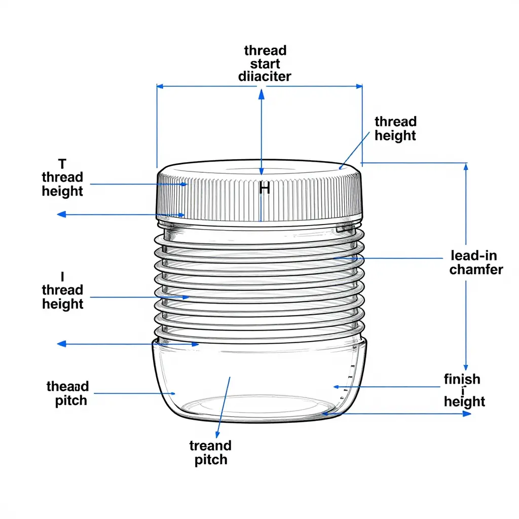
The Mechanism: Off-Helix Engagement
A matched pair engages along a single continuous helix. The closure’s first thread crest lands in the container’s thread root, the flank angle guides it, and the cap descends one pitch per revolution with the sealing land square to the finish top. Introduce a dimensional error and the crest lands on a flank instead of a root. The cap cants, the axis of rotation no longer coincides with the axis of the finish, and continued torque forces the threads to cut across each other. Each later revolution compounds the misalignment, which is why the damage usually shows on two or three thread turns rather than one.
Dimensions That Govern Closure Fit
Each critical dimension has a nominal basis in the container drawing and a tolerance band that has to be reconciled with the closure drawing. The failure modes below are not hypothetical; they are the ones that show up on the reject conveyor.
| Dimension | What It Controls | Nominal Basis | Typical Failure Mode When Out of Tolerance |
|---|---|---|---|
| T (thread major diameter) | Overall thread engagement; radial clearance to the closure minor diameter | Container drawing, referenced to closure T tolerance | Too large: cap binds and is forced; too small: cap rocks and skips the helix |
| E (thread root diameter) | Depth of the root that receives the closure crest; root-to-crest contact | Paired with T and H in the finish specification | A shallow root (E too large) leaves the closure crest riding high, causing partial engagement and thread stripping; a deep root (E too small) adds clearance and lets the cap rock |
| Thread height (crest to root) | Radial support and flank contact area | Derived from (T minus E) divided by 2 | Low thread leaves little flank bearing area; cap tilts under torque rather than descending |
| S (thread start position) | Angular and axial registration of the first thread relative to the finish top | Datum-referenced on the finish drawing | Off specification S rotates the helix entry point, so the cap starts one flank ahead or behind |
| I (inner bore diameter) | Plug/seal interference and the cap’s centering during the first turn | Bore tolerance on the container drawing | Oversize I removes the centering guide; undersize I creates interference that deflects the cap off-axis |
| Thread pitch | Axial advance per revolution; the rate at which the cap descends | Standard TPI or metric pitch shared by both drawings | Mismatched thread pitch guarantees progressive cross-threading after the first full turn |
| Thread flank angle | Guidance of the crest into the root; load-bearing contact | Stated on the drawing, often around 30 degrees for a symmetric profile, or an asymmetric buttress form | A different flank angle narrows the entry window and converts a normal lead-in into a collision |
| Lead-in chamfer geometry | Self-centering during the first 30-60 degrees of rotation | Chamfer angle and length on both parts | A short or blunt chamfer on either part eliminates the centering effect the capping head depends on |
| H (finish height) | Seating plane and total number of engaged turns | Finish drawing, measured from the sealing land | Short finishes reduce engaged turns; excess height pushes the cap onto an unthreaded section |
Nominal Mismatch Versus Process Drift
Two distinct populations of failure sit behind these dimensions, and they need different corrective actions.
Nominal mismatch is a specification error. The container drawing and the closure drawing were never reconciled – T on the bottle is generous, T on the cap is tight, and the tolerance stack-up leaves less than zero clearance at worst case. It appears on day one of a new SKU, is consistent across every cavity and every shift, and cannot be fixed by process adjustment. It gets fixed on paper first and in tooling second.
Process drift is a capability problem. The drawings agree, but the molded part no longer sits at nominal. Drivers include tooling wear on thread cores, cavity-to-cavity variation across a multi-cavity mold, resin shrinkage differences between lots and colors, and cooling-induced ovality that makes T and E vary around the circumference of a single finish. Drift shows up as a rising reject rate over weeks, as a defect concentrated in one cavity, or as a problem that appears only with certain resin batches. Dimensional records, not operator impressions, separate drift from mismatch – the same discipline packaging engineers apply when auditing formats across a rigid container range.
Why Slowing the Line Masks the Symptom
Reducing capping head RPM or line speed does three things, none of them corrective. It lowers the kinetic energy at first contact, so the cap deforms instead of visibly crossing the threads. It increases dwell time under torque, which can produce a cap that looks seated while sitting off-helix. And it caps throughput, hiding the defect behind a slower line that still leaks, still fails vacuum decay testing and still generates complaints. Speed amplifies the symptom; it does not cause it. A line that only runs clean at half speed is telling you its geometry is marginal – the caps in that run are failing a dimensional test, not a timing test.
Conclusion: The Neck Finish Is the Control Point
Cross-threading is a metrology problem dressed as a machine-setting problem. The control point is the neck finish: T, E, H, S, I, pitch, flank angle, chamfer and finish height, each measured against a drawing that has been explicitly reconciled with the closure specification. Establish SPC on those dimensions at cavity level, use functional and indicating gauges that reflect real engagement rather than single-point calipers, and run a formal capability study before blaming the capper. Do that and the head will run at full speed, because the geometry finally lets it.
Neck Finish Parameters vs. Observed Cross-Threading Symptoms
The table below is the evidence map: find the symptom on the filled container, trace it to the parameter that drifted, then confirm with the gauging method in the last column. The same fault logic applies across rigid screw-cap formats, including plastic cups for cold drinks and wider-mouth food tubs.
| Parameter | Definition | Typical Consequence When Out of Tolerance | Symptom Visible on the Filled Container | Verification Method |
|---|---|---|---|---|
| T dimension | Major (outside) diameter measured across thread crests at the gauge point | Crest interference on the first turn; loose or binding engagement; closure cocks on the helix | Skewed cap with a one-sided gap; shaved thread slivers under the cap skirt; cap spins without tightening | Go/no-go thread ring gauge; micrometer across crests; optical comparator |
| E dimension | Root (minor) diameter measured at the thread root between crests | Root too shallow (E large) leaves the closure crest riding high; root too deep (E small) adds clearance and lets the cap rock onto one flank | Cap jumps a thread under torque; inconsistent applied height bottle to bottle; plastic debris in the thread | Go/no-go thread plug gauge; optical comparator; contact (CMM) thread scan |
| Thread height (crest to root) | Radial depth of the thread form, roughly (T minus E) divided by 2 | Shallow thread carries less bearing area, so torque goes into tilting and crest shear rather than descent | Cap rocks under torque; polished or stripped crests; applied height inconsistent | Optical comparator or thread profile scan; CMM |
| S dimension (thread start position) | Axial and angular location of the first thread point relative to the finish datum | Closure helix does not match the bottle helix at first contact, so the cap starts crooked on revolution one | Cross-threading concentrated on one lane or spindle; caps tilted visibly; strip marks at skirt entry | Vision system or optical comparator indexing thread start to datum; thread-start gauge; CMM helix trace |
| I dimension (inner bore) | Inside diameter of the neck bore at the sealing land | Oversized bore lets the plug or liner ride loose; undersized bore fights the plug and skews the closure | Weeping at the closure seam; unevenly compressed liner; cap not seating flush | Bore gauge or pin gauges; air gauge; internal micrometer contact measurement |
| Thread pitch | Axial distance between adjacent crests | Pitch mismatch makes engagement advance or lag each turn, mimicking a capping-speed problem | Cap tightens partway then slips; helix marks offset around the skirt; leak at a consistent rotation angle | Thread pitch gauge; optical comparator crest-to-crest; thread profile tracing or CMM |
| Thread lead-in chamfer | Angled entry at the thread terminus that guides the closure onto the helix | Missing, short, or rough chamfer removes the lead-in, so the skirt edge catches the first crest | First-thread shaving and plastic debris at the fill line; nicked cap edge; cross-threading only on turn one | Optical comparator or toolmaker’s microscope for angle and length; contact profile scan; magnified visual per inspection plan |
| Finish height | Total vertical distance from sealing surface to the base of finish or neck support bead | Short finish limits usable engagement turns; tall finish moves skirt contact away from the tamper band seat | Tamper-evident band bridges or sits off the bead; applied height out of spec; low removal torque | Height gauge; calibrated caliper on a fixture; optical comparator with datum reference |
| Ovality / roundness | Departure of the thread or bore cross-section from a true circle, expressed as TIR or max-minus-min diameter | Localized tight and loose zones around the circumference; closure binds at one clock position and strips at another | Cross-threading clustered at a fixed clock position; cap cocked with one-sided gap; intermittent leak at one spot | Roundness gauge or dial indicator on V-block; three-point bore gauge; optical comparator with rotation stage |
The tolerance bands below are illustrative, not recommended limits: dimensional limits commonly held near +/- 0.10 mm, ovality near 0.15 mm TIR, lead-in chamfer roughly 0.5 mm to 1.0 mm at 30 to 45 degrees. Confirm against the released neck finish drawing and the closure supplier’s specification before rejecting or accepting a lot.
When cross-threading shows up on a filling line, work a fixed sequence: verify the specification on paper, measure the physical parts, then correlate those measurements with what the capper recorded. Each check below depends on the one before it, so do not skip ahead to machine adjustments until the preceding step has passed.
-
Retrieve and reconcile the drawings. Pull the container neck-finish drawing and the closure supplier’s drawing before touching a machine setting. Confirm that T (thread major diameter), E (root diameter), thread pitch, thread start position and tolerance bands agree. A mismatch here is a specification failure, not a capping fault.
-
Confirm resin and cavity records. Match the specified resin grade, documented shrinkage allowance and cavity identification for the sampled containers against lot traceability and the molder’s certificate of analysis. If any cavity runs a grade or shrinkage correction that was never validated for that neck tool, the check fails.
-
Measure after full cooling and conditioning. Take neck diameter and neck height on cooled, conditioned containers rather than parts straight off the mold, and accept only readings inside drawing tolerance after complete shrink.
-
Screen every sampled thread with go/no-go gauges. The go element must seat fully and the no-go element must not enter. Partial or forced engagement confirms a neck finish mismatch and outranks capping speed as a suspect.
-
Quantify ovality and flank geometry. Record ovality as maximum minus minimum diameter across the sealing land, and check flank angle and pitch with a dial bore gauge and thread profile tool. Fail the neck if ovality exceeds the drawing limit or the pitch deviation is large enough to shift the closure’s thread start.
-
Verify the closure against its own drawing. Measure closure T and E dimensions, thread pitch, and liner or plug depth with a calibrated micrometer and thread plug gauge. An out-of-tolerance closure produces symptoms indistinguishable from a bad neck.
-
Run a hand-application trial on measured parts. Apply closures by hand with a torque-limiting driver set to the specified application torque, count how many start off-thread, and fail the trial if any closure needs more than one attempt to seat.
-
Correlate capper data with the measured parts. Compare applied torque, application angle and reject counts from the capper’s torque/angle trace against neck and closure measurements from the same lot. Call a neck finish mismatch only when reject rates follow the dimensional outliers rather than head settings or line speed.
-
Document and quarantine. Record every measurement, gauge identification number, calibration date and pass/fail result on the audit form, then tag and hold the suspect container and closure lots until the out-of-tolerance dimension is corrected at its source.
Closure fit discipline applies across primary packaging: teams specifying companion items such as sauce portion cups should hold lids and containers to the same drawing-based verification routine.
Why Capping Speed Is a Misattributed Variable
When cross-threading appears, the fastest diagnostic conclusion is usually the wrong one: cut the capping speed and see whether the defect rate falls. It often does fall, briefly, and that partial improvement gets recorded as proof that speed was the cause. Speed changes how torque is delivered, not the geometry of the thread pair. It can modulate the severity of a mismatch already present; it cannot create one or correct one. The gap between those two statements separates a line that is stabilised from a line that is fixed.
What Speed Actually Controls
Capping speed governs two mechanical quantities: the ramp rate of application torque and the impact dynamics at first engagement. At higher speed the cap meets the neck finish with greater relative velocity and less time for the thread start to self-align before load is applied. The chuck also decelerates through a shorter arc, so any residual misalignment between cap axis and container axis turns into radial force instead of being absorbed by a compliant approach.
Where thread start and pitch already conform, the head absorbs this. A properly set capping head with correct clutch response, chuck centring and adequate container support tolerates a broad speed range without producing cross-threads. On a conforming bottle the same head design runs clean at 60 and at 200 containers per minute. Where the neck finish is marginal, the same speed change becomes visible because it amplifies a contact condition already outside tolerance. That is amplification of a symptom, not generation of a cause.
Can Speed Create a Geometric Mismatch?
No. Cross-threading requires the lead-in of the cap thread to enter the neck thread at an axial position and angular attitude that no flank contact can correct. That condition is a function of thread start position, pitch, thread depth, T and E dimensions, and the squareness of the sealing surface to the container axis. Speed carries no dimensional content. It cannot move a thread start, change a pitch, or alter a moulding. In causation terms it fails the counterfactual test: restore a conforming neck finish and the defect disappears at any speed within the head’s rated envelope; keep the non-conforming finish and the defect returns whenever the head is loaded faster than the mismatch can absorb.
The Confounders That Make Speed Look Causal
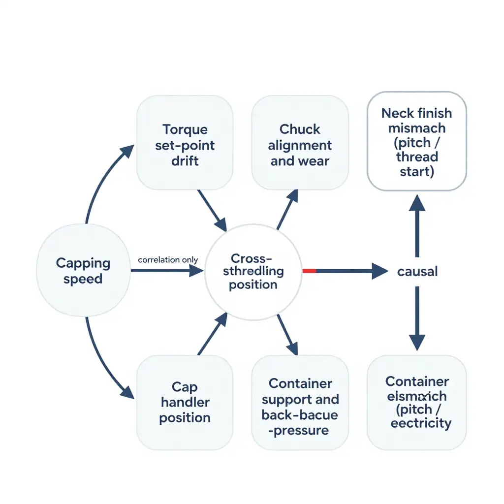
Speed is rarely changed in isolation. It usually changes as part of a line intervention, and several other variables move at the same time. Those variables carry the observed improvement.
- Torque set-point drift. Clutch springs relax, air pressure fluctuates, and set-points are re-taught after a changeover. A set-point that has drifted upward raises flank pressure on a misaligned start and shears thread; a downward drift produces loose caps that read as cross-threaded on the removal check.
- Chuck alignment and wear. Jaw wear, insert contamination and lost concentricity turn a small axial offset into a large radial force. Chuck condition often changes in the same maintenance window in which speed is reduced.
- Cap handler position. A handler set too low presents the cap before the container is fully supported; set too high, it drops the cap onto the finish. Both create the cocked entry that then gets blamed on speed.
- Container support and back-pressure. Insufficient top-load support or conveyor back-pressure lets the container rotate or deflect under the chuck. Lower line speed reduces the impulse transmitted to a poorly supported container – a support problem, not a speed problem.
- Container eccentricity. Ovality and neck-to-body offset increase with mould wear and with lightweighted containers. Eccentricity pushes the thread start out of the chuck’s self-aligning envelope at high approach velocity and back into it at low velocity.
Each confounder interacts with a neck finish mismatch rather than replacing it. A mismatch alone may produce a low, tolerable defect rate; a mismatch plus a worn chuck plus a high set-point produces intermittent, shift-specific failures. That intermittency is the signature of interacting variables, and it is why speed attracts blame: speed is the easiest variable to change and therefore the one changed first.
Application and Removal Torque When Engagement Turns Fall
Torque data make the mechanism explicit. With a capping head set-point of 1.1 N·m, reducing effective engagement turns through misalignment changes the character of the torque trace long before the cap is visibly defective.
| Effective engagement turns | Peak application torque (N·m) | Removal torque (N·m) | Interpretation |
|---|---|---|---|
| 3.0 | 1.1 | 0.95 | Full flank contact; clutch cuts out cleanly at set-point |
| 2.5 | 1.5 | 0.80 | Marginal seating, removal torque already low |
| 2.0 | 1.9 | 0.58 | Set-point reached before seating, flank slip |
| 1.5 | 2.7 | 0.36 | Interference dominant, cap cocked |
| 1.0 | 4.2 | 0.18 | Jam and strip risk, torque no longer tracks clamp load |
| 0.5 | 6.6 | 0.08 | Cross-threaded, removal torque near zero |
Figures are illustrative of the trend, not measured values.
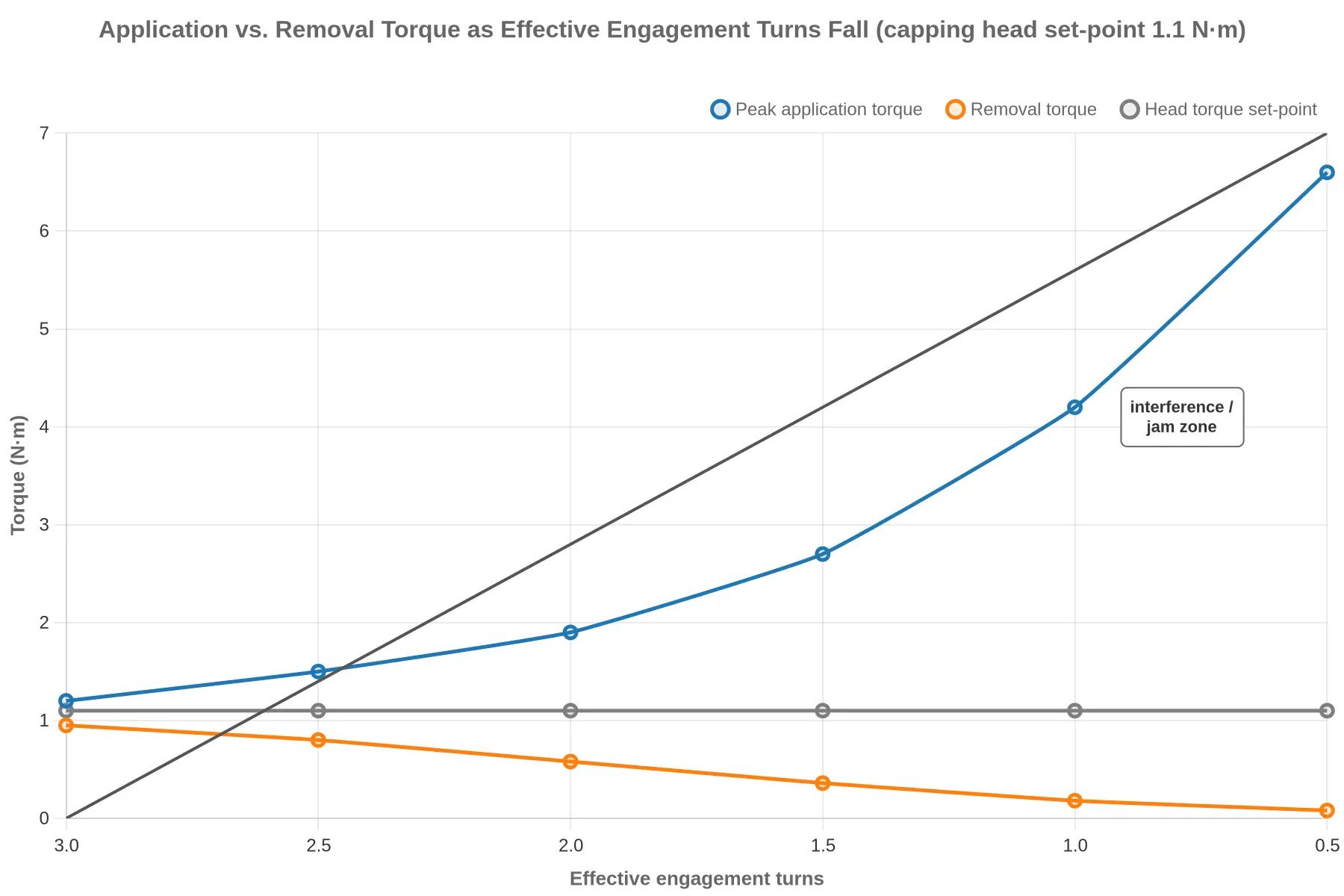
Once peak application torque exceeds the set-point, the clutch trips early and the recorded torque stops representing clamp load. Torque monitoring then reports a compliant cycle while the cap is not seated, which is how caps pass the inline check and fail at the leak test. Removal torque falls in parallel, because the cocked cap concentrates load on a smaller contact area and the engaged flank count cannot hold preload. Neither curve depends on speed once engagement turns are held constant; both are direct functions of geometric conformance.
Correlation Versus Causation in Practice
A correlation between speed and defect rate establishes that both variables respond to the same line condition. It does not establish direction. The analytical test is to hold the confounders fixed and vary only the neck finish: run a lot with confirmed pitch, thread start and T dimension against a lot with documented deviation, at identical speed, identical chuck, identical set-point. If the defect tracks the finish and not the speed, speed was never the causal variable. Packaging engineering teams specifying closures for rigid containers such as plastic cups for cold drinks can apply the same conformance-first logic when qualifying moulds and closure lots.
Analytical Conclusion
Speed adjustment addresses symptoms; neck finish conformance addresses causes. Lowering speed reduces the impulse applied to a marginal thread engagement and can suppress the visible failure rate, but the geometric non-conformance stays where it was, interacting with chuck wear, set-point drift, handler position, container support and eccentricity to produce intermittent defects. Qualify the neck finish against the closure thread specification, control the confounders as a set, and confirm capability at the full production speed envelope rather than at a derated one.
Cross-Threading Incidence vs. Neck Finish Conformance Across Speed Bands
Line speed and neck finish quality are the two factors named most often in a cross-threading investigation, and they behave differently when plotted side by side: one gives a flat response, the other a step change.
The chart below compares cross-threading incidence for two populations of the same container format, run on the same capping equipment with the same closure lot – containers whose neck finish dimensions were verified within tolerance, and containers with a documented deviation (T dimension out of spec, excessive ovality, or thread-start offset). It is one plant’s data, plotted against three capping speed bands.
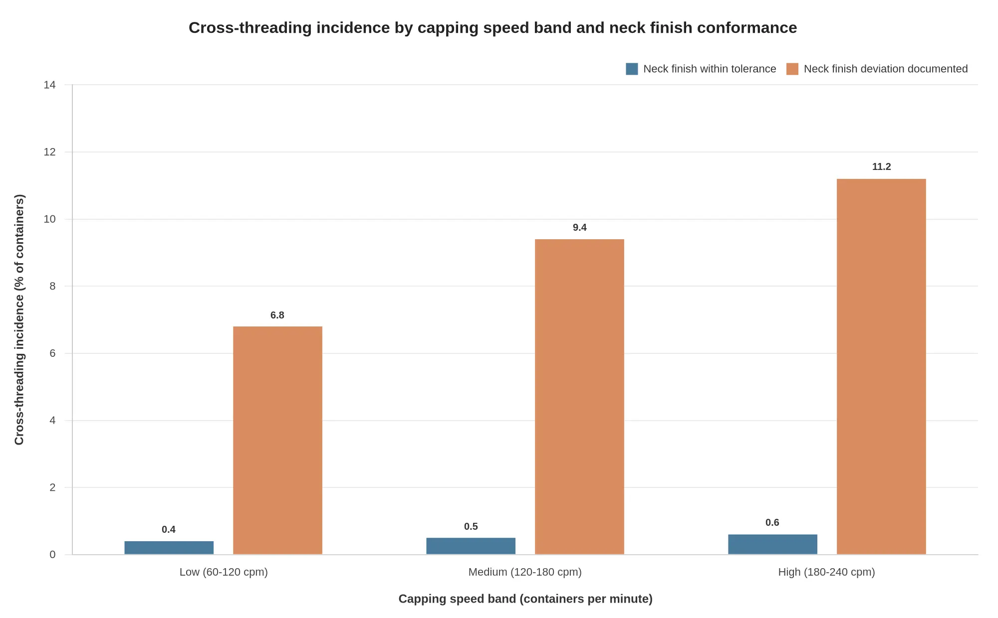
Reading the Two Series
The within-tolerance series barely moves. From the slowest band to the fastest, incidence drifts from 0.4% to 0.6% – a variation small enough to sit inside normal sampling noise for a line running a few thousand containers per shift. No inflection point appears, and no speed band where conforming containers suddenly begin to cross-thread.
The deviation series tells a different story. Incidence starts at 6.8% in the low band and climbs to 9.4% and then 11.2%. That is a seventeen- to nineteen-fold gap against the conforming population at every speed, and it is present before the line has accelerated at all.
| Speed band (cpm) | Within tolerance | Documented deviation | Ratio |
|---|---|---|---|
| 60-120 | 0.4% | 6.8% | 17.0x |
| 120-180 | 0.5% | 9.4% | 18.8x |
| 180-240 | 0.6% | 11.2% | 18.7x |
The ratio column is the part that matters for root cause analysis. If speed were the effective variable, the gap between the two populations would narrow or widen unpredictably as the line accelerated. Instead it holds at roughly eighteen to one. Speed is scaling an existing failure mode, not creating it.
Why Speed Keeps Getting Blamed
Higher line speed raises the container count per hour, so the absolute number of cross-threaded caps per shift increases even when the percentage does not. Operators see more rejects in the tote and more stoppages at the capper, and the intuitive conclusion is that the machine is running too fast. There is also a mechanical bias at play: at 180 cpm and above, a misaligned cap has less time to self-correct before the torque ramp completes, so a neck finish that was marginal at 90 cpm becomes visibly non-conforming at 200 cpm. The defect was always there. Speed only removed the recovery window that had been masking it.
This is why speed reductions so often “work” temporarily. Dropping from 200 cpm back to 120 cpm restores enough dwell time for a marginal thread engagement to complete, incidence falls, and the investigation closes with a line-speed setpoint instead of a corrective action. The deviation is still in the container population; it simply has more time to be forgiven.
What the Comparison Means for Your CAPA
- Suspect the container before the capper. When cross-threading appears after a container or closure change, pull retention samples and measure the finish before touching capper settings. For teams also specifying adjacent formats such as plastic cold-drink cups and containers, the same discipline applies: the interface geometry is the variable to control.
- Treat speed as a masking parameter, not a root cause. Record the speed at which the defect was first observed, but do not let it become the corrective action. If a speed reduction eliminates cross-threading, you have found a workaround.
- Stratify incidence data by container lot. Aggregate cross-threading percentages hide the bimodal distribution above. Splitting the data by neck finish conformance is what makes the deviation population visible at all.
A chart like this one is only as good as the dimensions behind it. If the incidence figures are not paired with verified T, E and ovality readings from the same containers, the two series collapse into a single blended average and the signal disappears. The measurement protocol below exists to prevent exactly that: it defines how to sample, hold and measure a neck finish so the data you stratify traces back to a specific cavity, resin lot and shift.
Measurement Method and Data Collection for Root-Cause Confirmation
Cross-threading is easy to blame on capping speed and hard to prove on neck finish, and the difference is measurement discipline. An inference is a plausible story. A root cause is a dataset that a bottle supplier, a closure supplier and a filler can all audit independently. The method below produces that dataset in an order that survives technical challenge.
Step 1: Compare Specifications at the CTQ Level
Start with the drawings, not the bottle. Put the container drawing beside the closure drawing, align both to the same nominal thread standard, and extract every characteristic that governs thread engagement. A mismatch rarely shows up as an obviously wrong diameter. It hides in thread start position, thread pitch, or the tolerance stack-up between the E diameter, the T dimension and the closure’s minor diameter.
| CTQ parameter | Container drawing | Closure drawing | Verification method |
|---|---|---|---|
| E (root diameter) | Nominal + tol | Relates to minor dia. | Air gauge, CMM |
| T (opening diameter) | Nominal + tol | Relates to plug dia. | Air gauge, comparator |
| S (thread start to top) | Nominal + tol | Thread entry | Optical comparator |
| H (finish height) | Nominal + tol | Skirt engagement | Caliper, CMM |
| Thread pitch / lead | Nominal + tol | Nominal + tol | Projector, CMM |
| Thread start angle | Datum-relative | Datum-relative | Optical comparator |
| Ovality (max – min) | Limit specified | N/A | Air gauge, CMM |
| Neck wall thickness | Nominal + tol | N/A | Sectioning, CMM |
Convert the two drawings into a single tolerance stack-up: worst-case closure minor diameter against worst-case container major diameter, then turn the thread-start angular offset into axial lead using the pitch. If the stack-up consumes the intended clearance, cross-threading becomes statistically inevitable at any capping speed, and that calculation alone reframes the investigation.
Step 2: Size and Stratify the Sample
Sampling has to be stratified, not convenient. Draw at least 30 containers per cavity per shift across three or more consecutive production lots, with first-off, mid-run and last-off subgroups so that mold temperature and cooling drift show up. For defect-rate estimates, use attribute samples of about 125 units per lot. Every unit carries its cavity number, shift, lot code and resin batch into the record; a sample without cavity traceability cannot separate a mold problem from a material problem.
Step 3: Select Instruments by Resolution, Not Convenience
Instrument choice determines which failure modes are visible at all.
- Go/no-go thread gauges. Attribute pass/fail with roughly 0.02 mm discrimination. Fast enough for line-side screening, but they confirm only gross mismatch and yield no ovality or positional data. Treat them as a screen, never as proof.
- Optical comparators and vision systems. Non-contact 2D profile measurement at 0.001-0.005 mm resolution, and the practical tool for quantifying thread start angle and root radius.
- Air gauges. Air plugs or air rings resolve 0.0005-0.001 mm at high throughput. A two-jet head reports a single diameter; a four-jet head exposes ovality as a spread and is the better choice for neck finish work.
- Contact CMM. 0.001 mm resolution in three dimensions, capable of thread start position and helix angle. Slow and sample-limited, so use it as the arbiter between parties rather than the routine tool.
Qualify every instrument through a gauge R&R study; measurement variation should stay under 10 percent of the tolerance being judged.
Step 4: Record Ovality and Thread Start Position, Not Only Average Diameter
An average diameter erases the two characteristics most likely to cause cross-threading. Record ovality as maximum minus minimum diameter at three heights along the finish, and thread start position as an angle in degrees relative to the mold datum, including its runout. A neck that is on nominal in mean diameter can still cross-thread every time if the thread starts 15 degrees late on one cavity and the closure engages before the thread is fully developed.
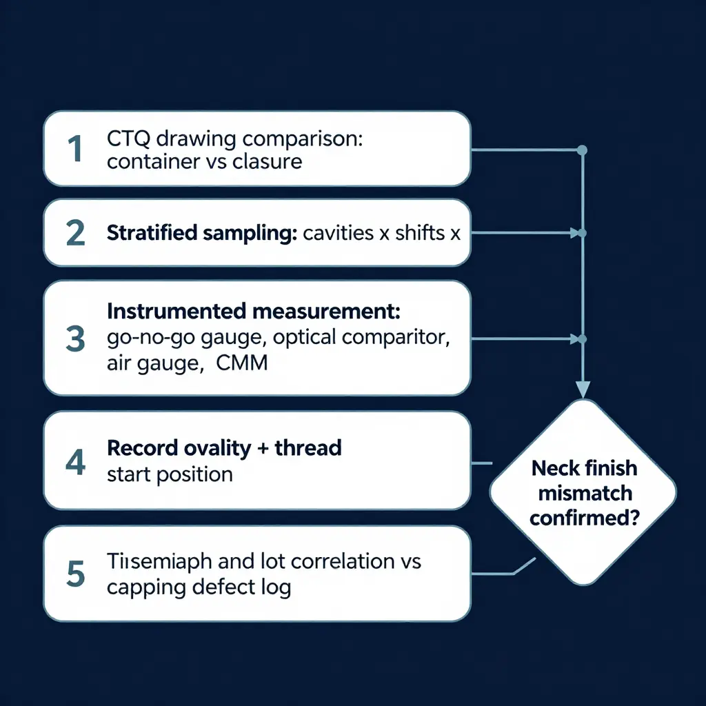
Step 5: Correlate Measurements to Capping Defect Logs by Timestamp and Lot
Join the two datasets on lot code and a timestamp window, typically plus or minus one hour around each defect event. Pull defect codes for cross-threading, cocked or high cap and torque rejects from the capping log, then test the association with a chi-square comparison of defect rate against the in-specification and out-of-specification groups. Calculate the lag between the first out-of-tolerance measurement and the first logged defect; a consistent lag confirms that the neck finish drifted before the line reacted. Closure lot, capping torque and spindle speed belong in the same extract so competing causes are tested rather than assumed. Where a wider packaging program is under review, comparing neck and lid interfaces across plastic cup and container formats helps benchmark normal engagement feel.
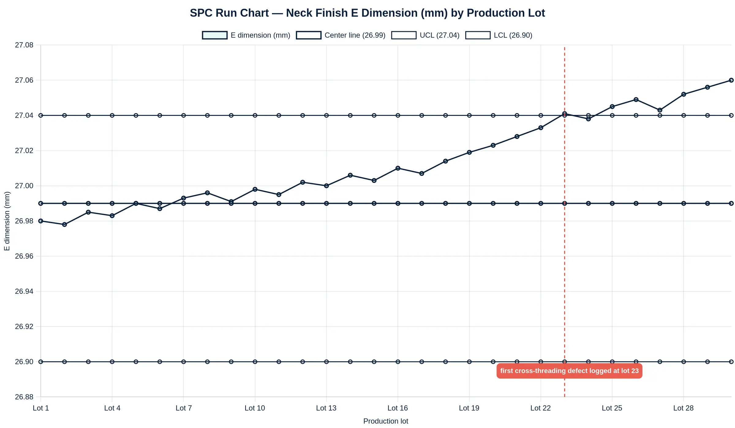
Step 6: Use SPC Run Charts to Catch Drift Before Defects Appear
Plot each critical neck finish dimension on an individuals and moving range chart, segregated by cavity, with limits calculated from a known-stable baseline rather than from the current data. Apply run rules for trends and stratification, and pair each variables chart with a p-chart of cross-threading rate from the capping line. The purpose is early warning: an upward drift in the E dimension across consecutive lots signals tool wear or cooling imbalance several lots before the first rejected cap.
Data Fields to Capture
- Gauge or instrument ID, calibration date, and operator
- Container lot, cavity number, shift, and resin batch
- E, T, and H dimensions with maximum and minimum values
- Ovality at three heights, thread pitch, and thread start angle in degrees
- Closure lot, capping torque at reject, and spindle speed at defect
- Defect code, event timestamp, and quantity affected per event
The conclusion is only as strong as the record. When drawings, stratified samples, resolution-appropriate instruments, positional data and time-matched defect logs agree, a neck finish mismatch stops being an opinion about capping speed and becomes a documented characteristic failure with a corrective action attached.
Diagnostic Sequence at a Glance
The diagram compresses the investigation into its decision order. Read top to bottom: the visible symptom, then the dimensional and tooling causes behind it, then specification correction. Working the boxes in order blocks the most common shortcut on a filling line – adjusting capping torque or spindle speed before the neck finish has been measured against its drawing.
How the six boxes map to the investigation:
- Defect observed – cross-threaded, cocked or stripped closures caught at the capper or in downstream inspection.
- Capping parameters reviewed – torque, application force, chuck alignment and line speed documented, not altered.
- Dimensional verification against specification – closure and container drawings pulled and compared side by side.
- Critical neck finish dimensions measured – T, E, S, I, H and thread-crest geometry checked with the correct gauges on a statistically valid sample.
- Supplier and cavity correlation – out-of-spec parts traced to a specific mold cavity, lot or tooling revision.
- Corrective specification action – drawing, tolerance band or tooling corrected and locked into the approved specification.
The boxes are intentionally unlabeled, so the numbering above is the working reference for a QA/QC review, a supplier corrective action request or a line-side troubleshooting meeting. Print it, pin it to the capper, and walk the sequence in order. The order is what separates a specification fix from a recurring line stoppage.
Corrective and Preventive Actions Across the Supplier Chain
Once a neck finish mismatch is confirmed as the root cause of cross-threading, the response stops being a line-side adjustment and becomes a documented, supplier-wide corrective and preventive action. The goal is to make the thread geometry of every cavity, lot and delivery capable of engaging the closure without misalignment, and then to prove it stays that way. Each action below has an owner.
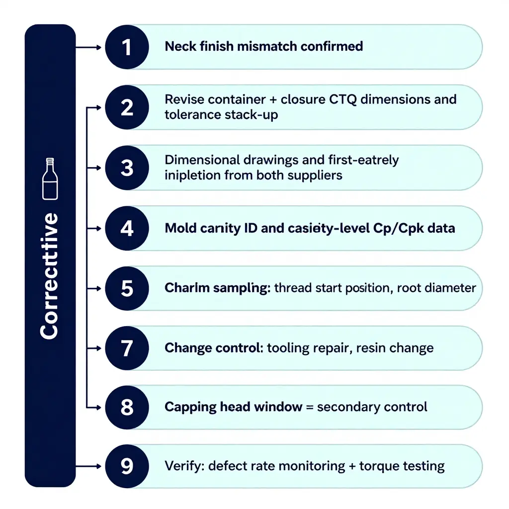
1. Re-baseline the specifications: define CTQ dimensions and a joint tolerance stack-up
Packaging engineering owns the rewrite. Container and closure specifications have to be revised as one paired document, not two independent drawings. CTQ dimensions include T (thread outside diameter), E (root diameter), S (thread start from the top of the finish), thread pitch and lead, neck diameter, finish height, and the closure’s own thread engagement depth and liner compression range – the part most often neglected.
The stack-up gets done jointly and agreed in writing. Container and closure tolerances cannot simply be added in the same direction; the team has to show, by worst-case and by statistical (RSS) methods, that the assembly still engages at the extremes of both parts. Where the stack-up fails, the specification changes, not the cap torque.
2. Require dimensionally capable drawings and first-article inspection reports
Procurement updates purchase orders and quality clauses; supplier quality enforces them. Both the container supplier and the closure supplier submit fully dimensioned drawings – no reference-only or “typical” callouts – plus a first-article inspection report with actual measured values rather than pass/fail ticks. Datum schemes and measurement methods (optical comparator, CMM, go/no-go gauges) belong on the drawing so results from two suppliers can be compared directly.
3. Mandate mold cavity identification and cavity-level capability data
A single “mold average” capability number hides the one cavity producing out-of-tolerance necks. Supplier quality requires permanent cavity identification on every container and closure, with capability reported per cavity (Cp/Cpk on the CTQ dimensions, at least 30 consecutive parts per cavity). Any cavity below the agreed Cpk threshold is quarantined for tooling correction before shipment. Without cavity traceability, defect investigations become guesswork.
4. Establish inbound inspection sampling for thread start position and root diameter
QA/QC builds the sampling plan around the two dimensions that drive cross-threading most directly: thread start position (S dimension and angular start) and root diameter. Use a defined AQL with a tightened inspection level during the containment period, and specify gauge type, sample size and the reaction plan for any nonconformance. The same logic extends to other molded formats the plant runs, such as plastic cups for cold drinks, where finish tolerance discipline is equally decisive.
5. Align co-packer and contract packager acceptance criteria
Packaging engineering and QA/QC issue the revised specification to every co-packer and contract packager, along with the same gauge set or measurement protocol. Two acceptance criteria for one product guarantee arguments and drifting yields. Document the co-packer’s sign-off, and audit the first production run against the new limits.
6. Control change notification for tooling repairs and resin changes
Supplier quality and procurement write a mandatory notification clause: any mold repair, cavity insert replacement, thread-core polishing or resin change – including a like-for-like supplier swap – requires advance notice and a fresh dimensional report before parts ship. Unannounced tooling work is a common source of recurring neck finish mismatch.
7. Position capping head setup windows as a secondary control
Production engineering documents capping head setup windows (torque range, cap application height, head alignment, gripper condition) as a secondary control layer. Setup windows absorb normal variation. Used to compensate for an out-of-spec neck finish, they trade line speed for cross-threading and seal failures.
Verifying Effectiveness
QA/QC closes the loop with two quantitative checks. First, cross-threading defect rate per shift and per supplier lot, with sustained reduction to baseline as the target. Second, application and removal torque plus bridge and back-off checks on samples from every run. If the defect rate or torque spread does not return to capability, the CAPA reopens at the specification level.
| Function | Primary action | Verification evidence |
|---|---|---|
| Packaging engineering | Revise paired container/closure CTQ specs, joint tolerance stack-up | Signed stack-up analysis, released drawing set |
| QA/QC | Inbound sampling plan, co-packer alignment, torque testing | Inspection records, defect rate trend, torque data |
| Procurement | Quality clauses in PO, change-notification terms | Contract language, supplier acknowledgements |
| Supplier quality | FAIR review, cavity ID, per-cavity Cp/Cpk, audits | Capability reports, mold cavity maps |
| Production engineering | Capping head setup windows as secondary control | Setup sheets, head audit results |
Where the Investigation Landed: Verified Root Causes
Once the corrective actions were validated, every confirmed case traced back to a single verified cause in one of six categories. The shares below come from one investigation and give a rough sense of where the exposure sits. They reinforce the earlier point: the defect originates upstream, at the interface between bottle and closure, not in how fast the capping head travels.
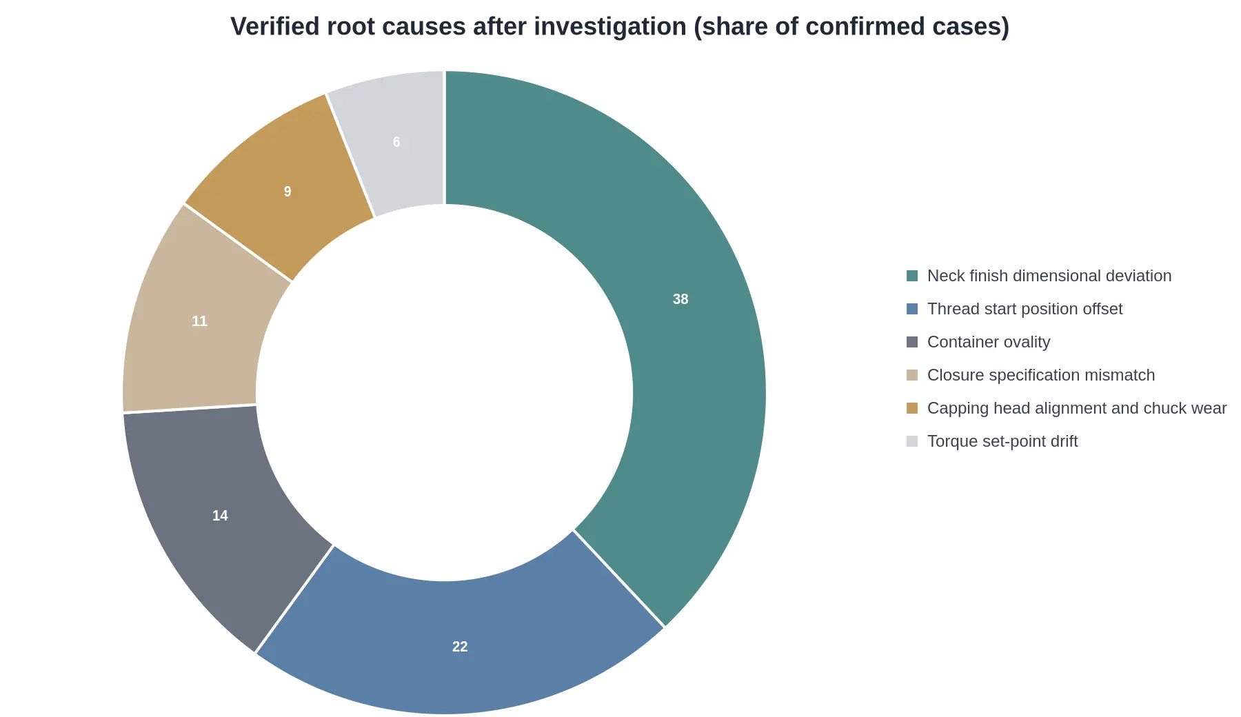
Shares are rounded to whole percentages and sum to 100%. Treat them as an order-of-magnitude breakdown of one investigation, not as a benchmark for every line.
Reading the Breakdown
- Neck finish dimensional deviation – about 38%. The largest block. Diameter, thread depth or finish height outside tolerance forces the closure to start off-axis.
- Thread start position offset – about 22%. A start point that is rotationally displaced makes the cap engage a partial thread, then jump and cross.
- Container ovality – about 14%. Ovality changes the effective thread pitch around the circumference, so engagement is inconsistent from one clock position to the next.
- Closure specification mismatch – about 11%. A liner or thread profile that does not match the declared finish will cross-thread even on a perfectly moulded bottle.
- Capping head alignment and chuck wear – about 9%. Real, but comparatively small – and a maintenance item, not a line-speed problem.
- Torque set-point drift – about 6%. The smallest verified category, and usually a symptom of the causes above rather than an independent one.
Two things stand out. Roughly three quarters of confirmed cases (neck finish deviation, thread start offset and ovality) sit in the container’s neck geometry, which is why incoming dimensional checks belong at the top of the control plan. The factors an operator can adjust on the fly – head alignment, chuck condition, torque set-point – account for about one case in seven. That asymmetry explains why chasing the problem with speed and torque tweaks frustrates: the machine is being asked to compensate for a neck finish that is already out of spec.
Frequently Asked Technical Questions: Cross-Threading on Screw-Cap Lines
Can reducing capping speed eliminate cross-threading?
No. Speed changes how often a geometric misalignment shows up, not whether it exists. If the closure thread lead-in lands above or below the mating neck thread, slower spindle travel still crosses the threads, only less often. Gauge the neck finish and check neck perpendicularity before touching line parameters.
Which neck finish dimension matters most for thread engagement?
The T dimension (major thread diameter) comes first, together with thread-start position and neck perpendicularity to the base. Cross-threading happens when the closure thread misses the lead-in, and an out-of-tolerance T or a displaced thread start moves that engagement point. Verify T with a calibrated go/no-go gauge, then E (root diameter) and I (inner diameter).
How do you distinguish a neck finish mismatch from a closure defect?
Run a cross-matrix trial: known-good closures on suspect containers and suspect closures on known-good containers, roughly 30 pieces each at a fixed application torque. Failures that follow the containers point to a neck finish mismatch; failures that follow the closures send you to closure thread dimensions and cavity tooling. Confirm with gauge readings on both components rather than visual inspection alone.
Do liners or application torque affect cross-threading?
Liners do not cause it. Thread engagement happens before the liner contacts the sealing land, so liner thickness or material cannot start a thread wrong, though both affect seal integrity and back-off. Application torque governs strip and removal torque rather than engagement geometry; excessive torque can shear or cam out threads, which is a separate failure mode. Verify torque with a calibrated torque tester per ASTM D3198, which covers application and removal torque; ASTM D2063 covers torque retention after storage.
How should neck finish tolerances be written into a purchase specification?
Name the finish standard explicitly – SPI 400 or SPI 410, for example, or a multi-start M-style finish – and give T, E, I, S and H as stated minimum and maximum values. Add neck perpendicularity, ovality limits, resin grade, gauging method, AQL sampling plan and the 23 °C conditioning temperature. Specifying the gauge type is what makes supplier and buyer measurements comparable.
How frequently should neck finish dimensions be re-verified?
Gauge T, E and I on every incoming lot from an AQL-based sample. Perform a full dimensional audit quarterly, and immediately after any mold change, cavity repair, resin supplier change or tooling refurbishment. Re-verify after events that can distort containers, such as temperature excursions or pallet damage in transit.
Conclusion: Governing the Container-to-Closure Interface
The evidence points to a dimensional and geometric problem rather than a dynamic one. Cross-threading on the filling line starts at the container-to-closure interface, where thread start position, lead and pitch, root and crest geometry, ovality and finish height tolerance stack-up decide whether a closure engages cleanly on the first rotation. Capping speed only governs how much force and rotation reach that engagement; slowing the chuck reduces the symptom without restoring conformance. Treat speed as the root cause and you misread the defect, and any neck finish mismatch left in the specification will resurface at another line speed, another capper or another lot.
The control hierarchy follows. Specification alignment comes first: container and closure drawings must reference the same finish designation, with thread dimensions and start tolerances co-owned by both parties rather than implied. Cavity-level capability comes second, measured per cavity on the thread profile and roundness instead of lot averages, because multi-cavity molds do not distribute finish variation evenly. Inbound verification comes third: go/no-go gauges, applied-torque and seal-integrity checks, and matched-lot application trials that confirm the two halves of the interface behave as specified. Line-side setup – rail height, chuck alignment, top-load, application torque – comes last. It is a fine-tuning layer that protects a conforming interface and cannot manufacture conformance that was never specified.
For procurement and packaging engineering, the consequence is a change in where specifications are written, transferred and verified. A purchase order that describes only the container leaves the interface to chance, so the controlling dimensions, tolerances and inspection method have to be defined at the neck finish level and confirmed by functional cap application rather than by visual lot inspection. The same discipline reaches any format where component fit carries risk: screw cap plastic food containers alongside sauce portion cups, plastic cups for cold drinks and paper food trays all depend on format consistency being specified at the interface and verified before material reaches the line.